|
|
 |
| Home | Company | Contacts | Order | Accomplished projects | Links |
| ||||||
|
|
"SR LTD" Company Ukraine, Dnepropetrovsk, Artema St. 19/61 Phone number: +38(067) 630-12-09, +38(067) 630-12-08 ORDERSEND A MESSAGE |
APCS OF OXYGEN UNIT1. Description of controllable objectAir separation plant АК-6-2 is intended for production of gaseous and liquid oxygen and nitrogen. АК-6 plant is represented by cryogenic system, which works on the principle of gradual air-cooling to the temperature of its liquefaction with subsequent liquid air disaggregation by rectification method. Cold required for air liquefaction and refrigeration loss coverage is achieved due to expansion of compressed air in turbine expansion engines. Plant operation is arranged by low-pressure circuit. Air in volume flow rate 32000 m3/hour, compressed in turbine compressor to pressure 5.2 kgf/cm2, enters air-cooling unit, where it is cooled down to temperature about 20°С with water. Then the air enters regeneration group, consisting of two pairs of regenerators 1-4th with built-in coils for withdrawal of dry products. Passing through regenerators, air is cooled down to saturation temperature. At the same time in certain zones throughout the height of regenerators, moisture freezing-out takes place, carbon dioxide, hydrocarbons on regenerator packing. When air passes through one regenerator of pair, back stream passes through the second one, which removes impurities from packing, deposited during direct air blasting. In the equipment of unit (rectification towers, condensers, heat-exchange units) air separation into straight products: oxygen, nitrogen is performed. Equipment located outside the air separation unit is intended for air precooling, unit heatup, absorbers regeneration, liquid evaporation, drained from separation unit equipment. 2. Functions performed by systemAPCS performs the following function package - automatic control of oxygen unit operation with observance of predetermined process modes, with maintenance of preset process parameters; In the second (upper) level system fulfills production process display functions, interaction with operator, data collection and storage, data communication with lower level. In addition control of unit heating conditions exists by signals from regenerator centre (only for АК-6 unit) and regenerators switching in modes: “Manual”, “Remote shift”, which were not provided by standard system. 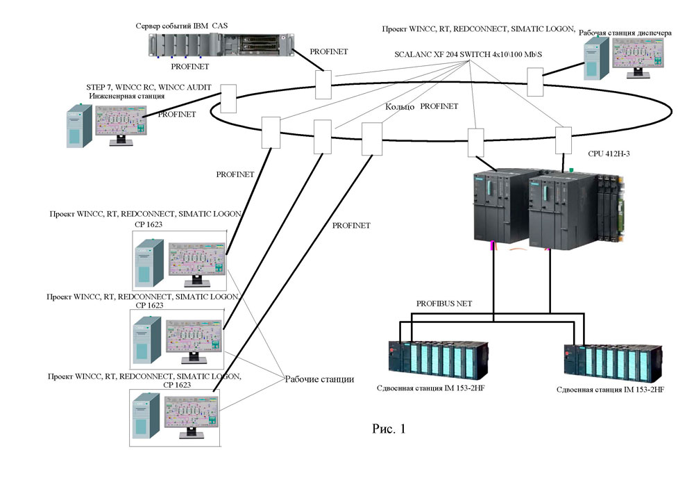 APCS structural diagram of oxygen unit is given in Figure 1 3. System structure and operation.The system has a hierarchical two-level control structure: 1) lower (first) level - instrumentation and control equipment and SIEMENS programmable redundant controller series SIMATICS7-400H. Work with input/output signals is executed using redundant assemblies of remote periphery series ET 200M-IM153-2HF and l/O-modules of the same series recommended by SIEMENS guide book (No.6ES7988-8HA10-8BA0); 2) upper (second) level – three operator stations identical in functionality, PC-based with TFT displays 24" with display system designed in SKADA WINCC 7.0, connected via PROFINET with lower level programmable controllers. Also in the second level engineering station with factory-set engineering software packages STEP-7 and WINCC 7.0 is provided for automation and display software development, and existing software maintenance, and events server, IBM server PC-based and CAS-pack (historical data storage of facility operation). The server has a capability of operator stations connection (in perspective) from АКар-6 oxygen unit. For supervision of IT personnel actions in control logic and display layout WINCC/AUDIT RT V7.0 software package is provided, EXECUTION OF CHANGES REGISTRATION LOG, For supervision of operating personnel actions Simatic LOGON software package is provided. 1. Purpose.This system is intended for АOU operation parameters tracking, their archivation and recording, and changeover valves operation control. 2. Description of general operating principles of the system.Display system is represented by windows pack, by means of which operator can monitor sliding shutters of the unit, control analog data, observe them in the form of diagrams, and operate switching modes of the first and second pair of units. Display is split into 3 main parts – top menu (always visible), bottom part– bottom menu (always visible), by means of which forms switching is performed, central part – various forms are displayed in it. 1) Top menu  RESET – toggle-switch position “EMERGENCY RELEASE” on control panel. Green – released, red – pressed. 2) Bottom menu  Switch to the section or window is performed by means of mouse pointer approach to the button and left mouse button click or pressing a relevant function button. General principle of analog data display: - signal name, its current value and units of measurement are displayed; General principle of sliding shutters display – name of sliding shutters, position of which is analyzed, is indicated with large bold letters and in case of status change (closed/open) the colour of sliding shutter changes and this status is entered in log register. Sliding shutters, not included in the system, are headed with smaller letters and their colour is unchanged – white. In case of some process interlock response, in the upper window the appropriate message will appear (with concurrent record in log register), and on logically associated screen red lamp and a text box will flash. (For example, “No air through electric heater” – a message will appear above, while the lamp and text box will be shown in the Absorbers window). F1 – open this document. 3. Message log.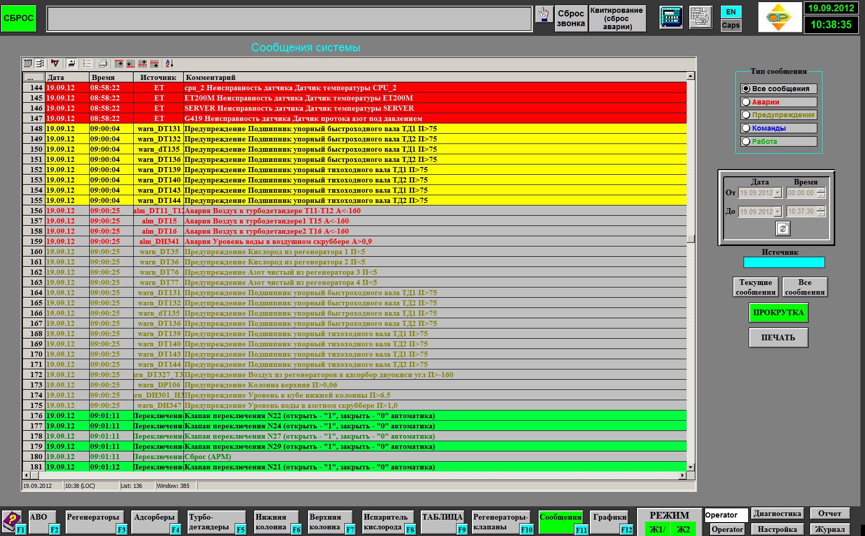 Message box enables to read messages: - Alarms (red), which happened not earlier than 60 days ago. In “Date” column date of message is specified, in “Time” column – the time of day, in “Source” column – group name, in “Commentary” column – message text. - solid colour – message received; Switches located on the right of message box, are displayed in message box: - Switch “Current messages” – only active (not acknowledged and not sent) statuses. Group “Message type”: - Switch “All messages” – enables to read alarm messages and commands. If we enter the item number (or symbols, encountered in title) in “Source” window, SQL data-base query will be executed and message reading is carried out only for that mechanism or item, in which title entered symbols are encountered. Click on the date will open a calendar for selection of start and end dates of reading. After selection of the desired time limits press the button “Update”. These options are available only if you select “All messages”. 4. Diagrams.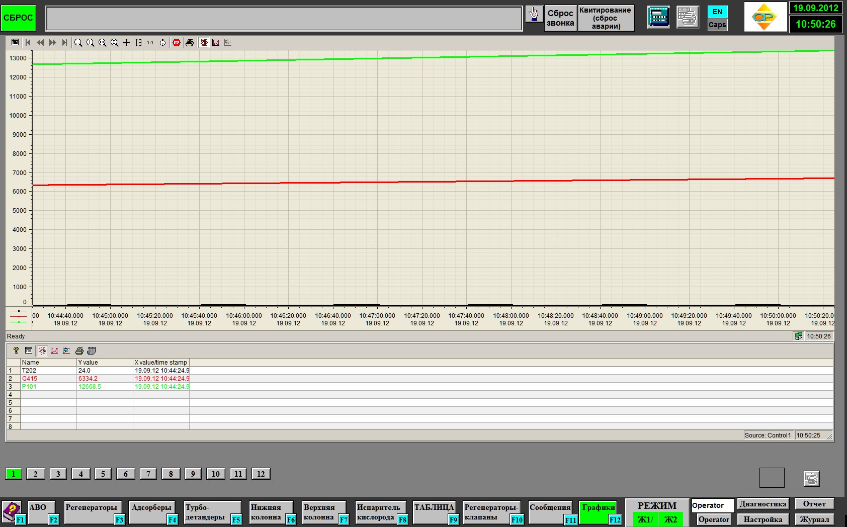 This form is intended for review of measured values diagram in any combinations. Owing to using of current version of SCADA WinCC system, user can configure each diagram for review of the required values and this information will be stored in project, therefore, at window reopening (even after computer rebooting), all configured diagram variables will be restored. 5. Application. ACU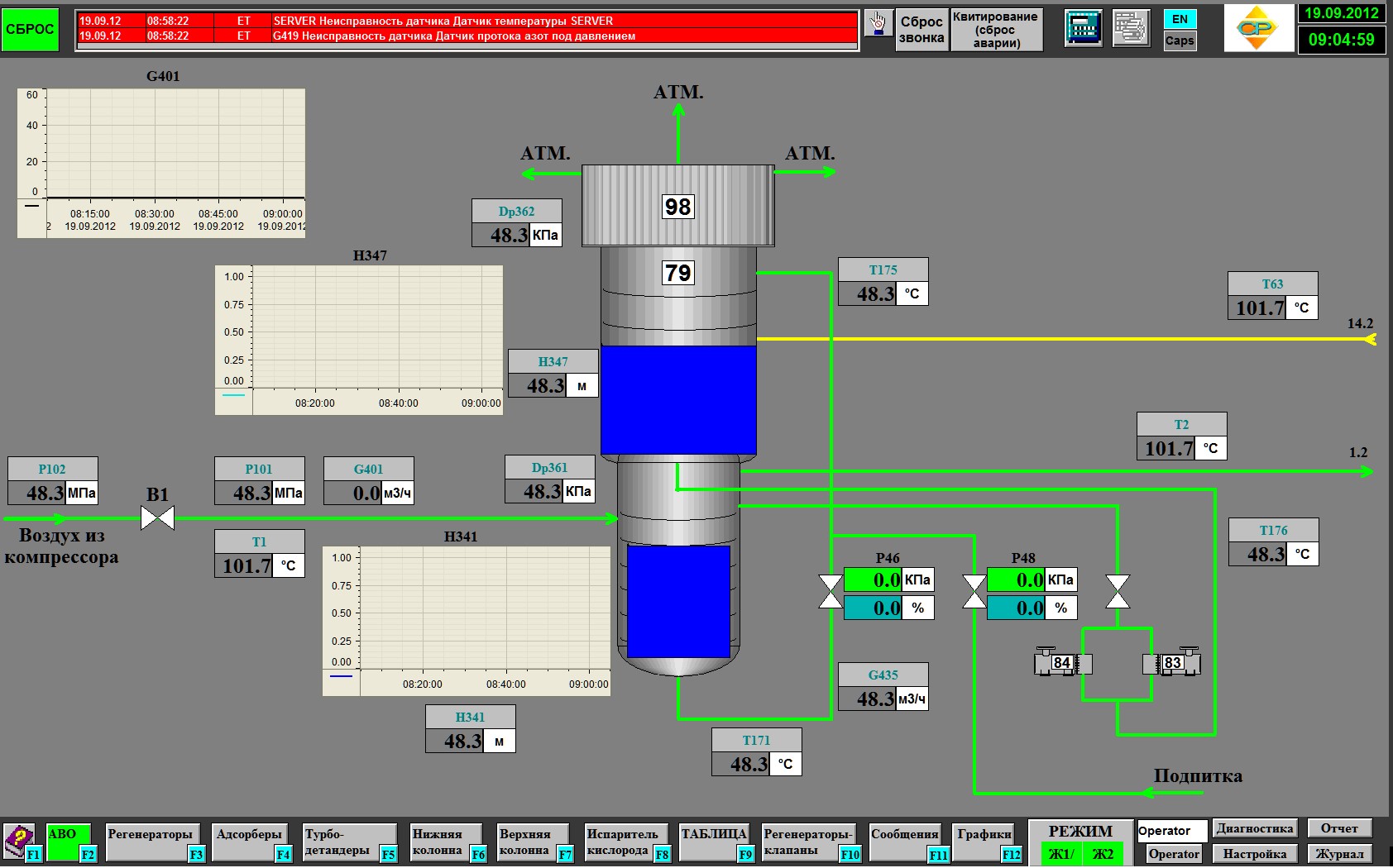 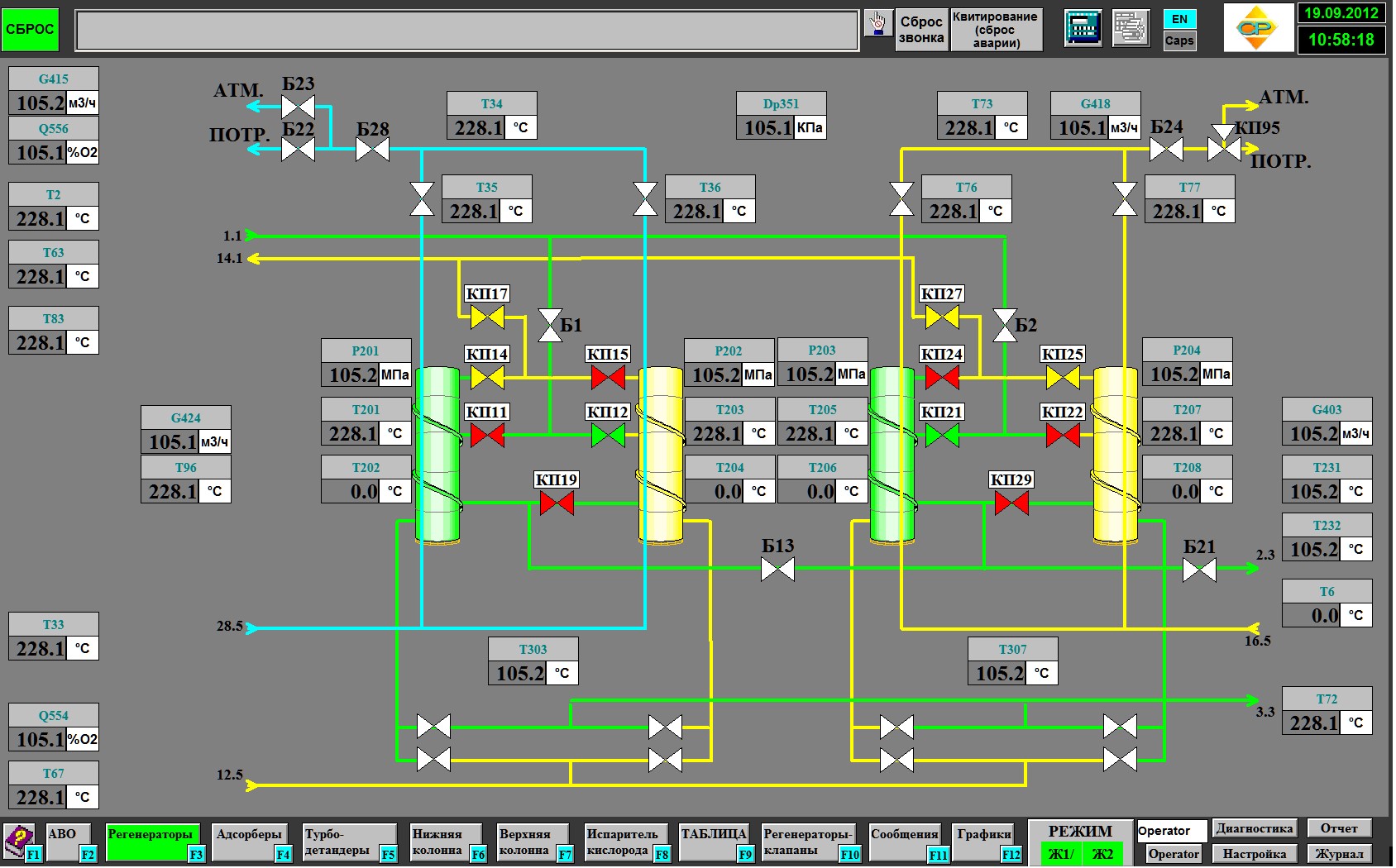 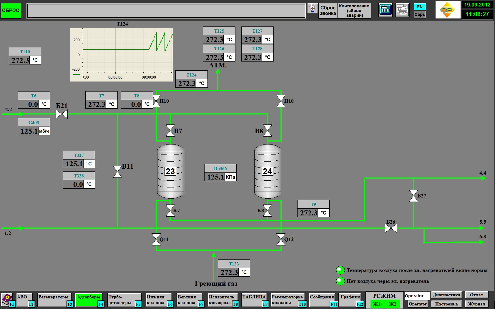 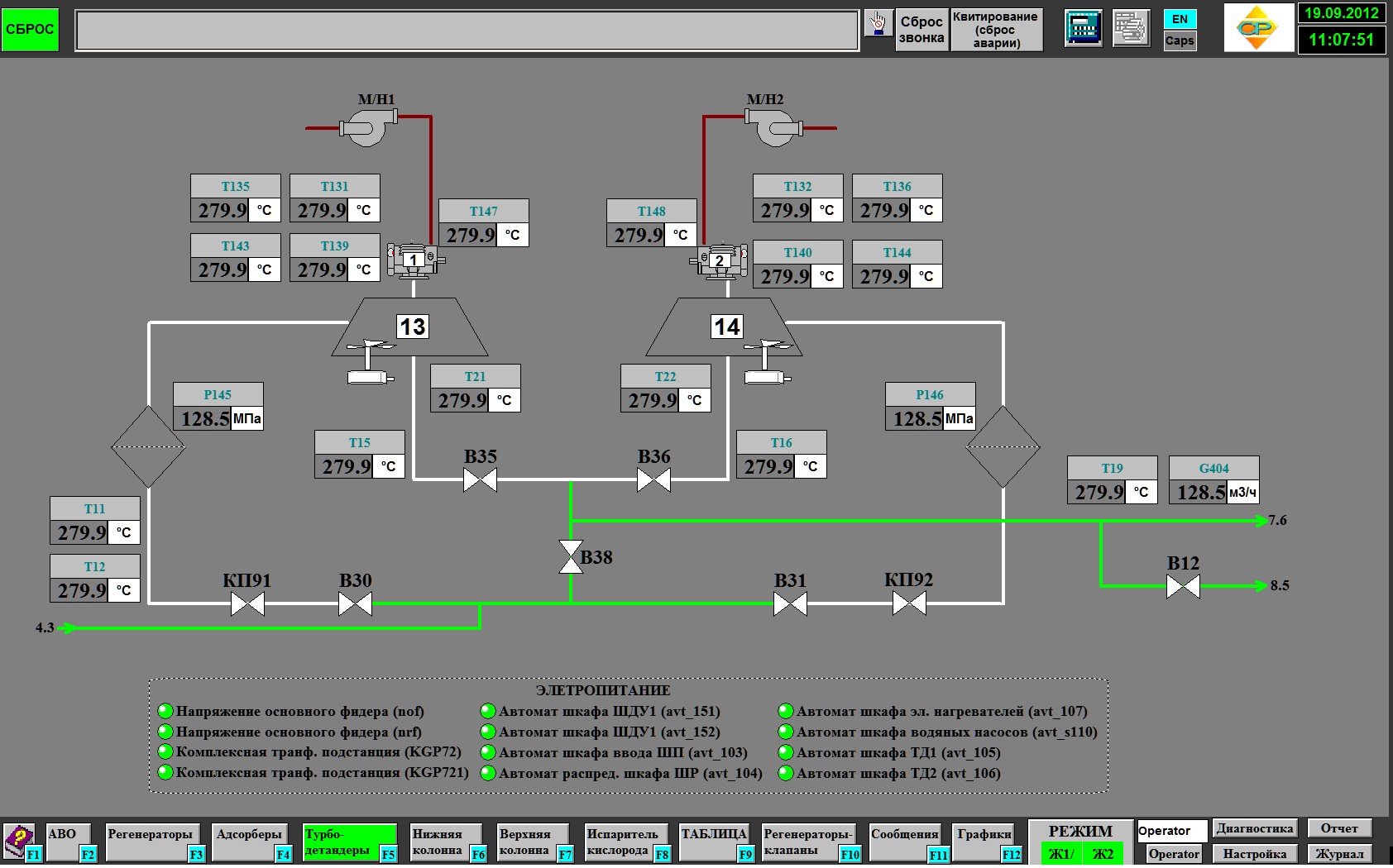 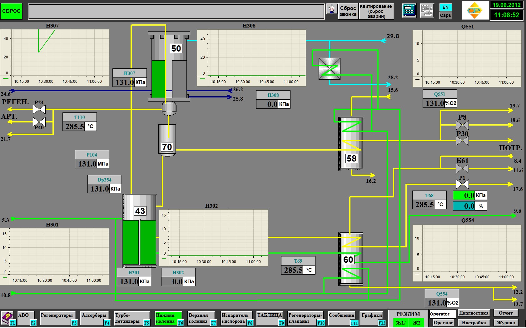 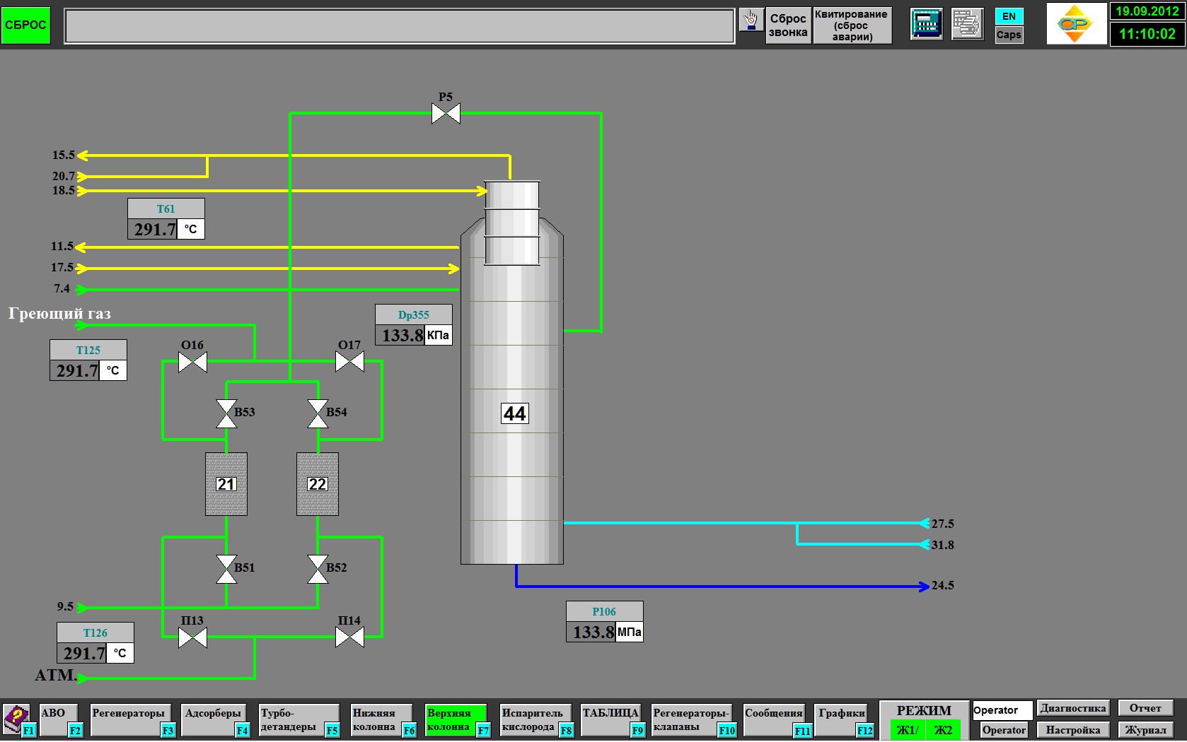 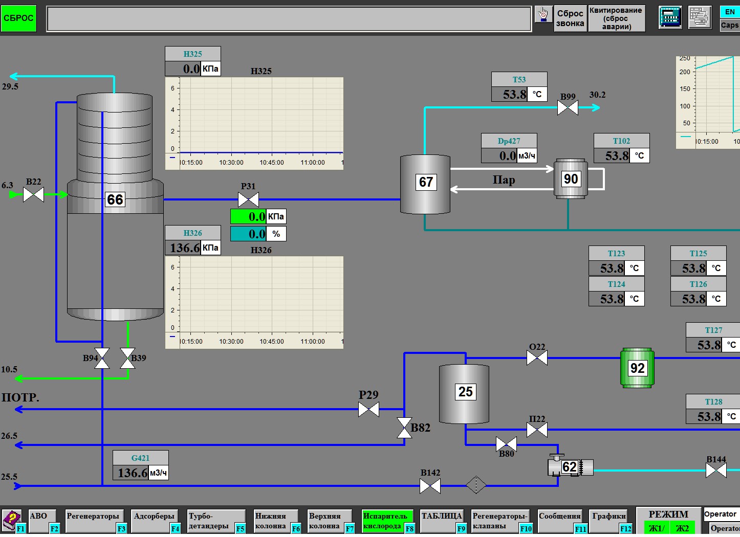 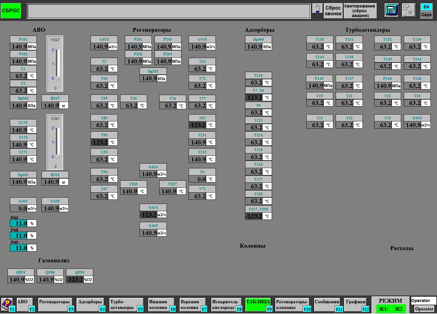 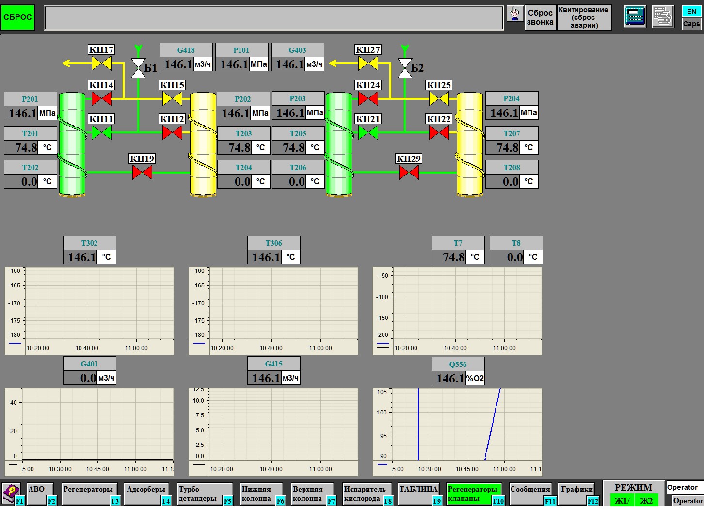 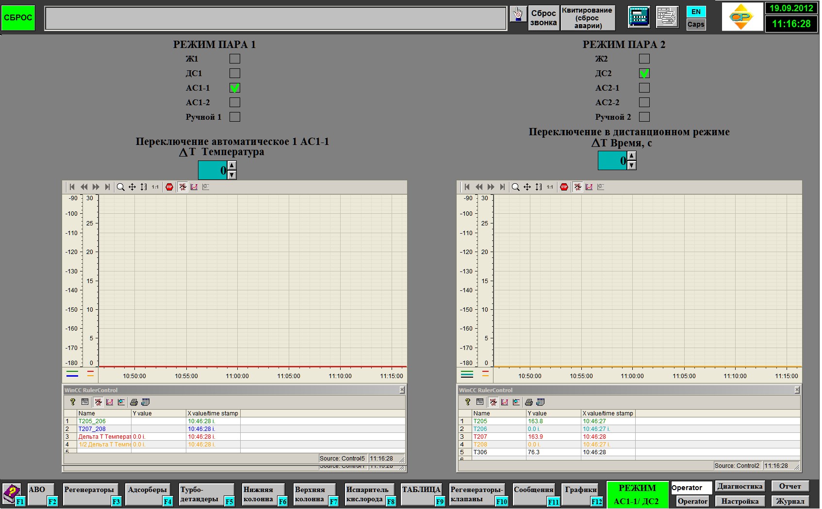 |
|
Сreator & support: InterBiz |
Copyright © 2006 “SR LTD” |